martes, 29 de enero de 2019

Circuitos acondicionadores de señal (CAS) con amplificador operacional

Circuitos acondicionadores de señal CAS con amplificador operacional 

Un circuito acondicionador de señal permite adaptar los niveles de entrada de una señal a otros niveles de voltajes, para que asi, estas señales puedan ser adquiridas en la siguiente etapa del circuito que se diseñe:

La mejor manera de explicar es con un ejemplo: 
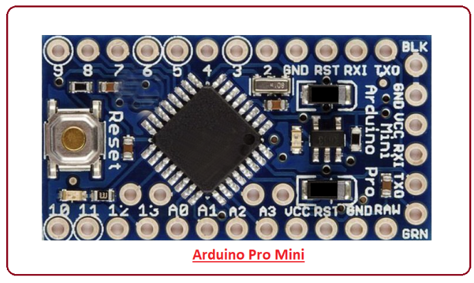
Se desea que una entrada de un sensor Lm335 (10mv/°C) rango del sensor  -10 a 100°C
Se trabaje de 0°C a  50°C
Es decir  0°C salida 0  Voltios
Y  a   50°C salida 5  Voltios 
El sensor entrega a:
 0°C    -------- > un voltaje de 2.73v
50°C   -------- > un voltaje de 3.23v 
Paso 1.  Dibujar una grafica donde se observe la salida deseada. 


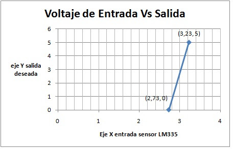
Podemos  observar dos pares de puntos en la grafica

Tabla 1. Puntos de la grafica

Entrada (X)
Salida(Y)
Punto Inicial
2,73
0
punto final
3,23
5
 Paso 2.  Como se quiere una salida  lineal. Esto quiere decir que la grafica anterior es la grafica de una recta. Por lo tanto podemos hallar la pendiente (m) con la ecuación (1),  donde la salida es (Y) y la entrada (X) 


Ahora reemplazando en la ecuación (1) los datos de la tabla 1.


Paso 3.  Usamos la ecuación (1) para encontrar la ecuación de la recta. 
Ahora reemplazamos los valores iníciales en la ecuación (2) y el valor de la pendiente
Esto quiere decir Y es la salida del operacional y X la entrada del sensor


 Paso 4.  Usamos Amplificador operacional en configuración sumador
Como es inversor  primero invierto señal de entrada para que al final salga positiva


Ahora implementamos en sumador


Elegimos RF = 100k, puedes elegir la que quieras.
De la ecuación (3) podemos observar que la ganancia del sensor es 10,  acordándonos que la ganancia del operacional para el sensor está dada por.


Ahora  ponemos un voltaje VR cualquiera o mejor el más conveniente, para este ejemplo se utilizara VR = 15V, de la ecuación (3) se puede obtener.


El circuito final es. Para una la ecuación:   con su zener de protección a la salida 


Referencias:
[1]http://www.vallecompras.com/store/index.php?option=com_content&view=article&id=14%3Acircuitos-acondicionadores-de-senal-con-amplificador-operacional-cas

jueves, 17 de enero de 2019

The ESP8266 ESP-01

The ESP8266 ESP-01
 is a Wi-Fi module that allows microcontrollers access to a Wi-Fi network. This module is a self-contained SOC (System On a Chip) that doesn’t necessarily need a microcontroller to manipulate inputs and outputs as you would normally do with an Arduino, for example, because the ESP-01 acts as a small computer. Depending on the version of the ESP8266, it is possible to have up to 9 GPIOs (General Purpose Input Output). Thus, we can give a microcontroller internet access like the Wi-Fi shield does to the Arduino, or we can simply program the ESP8266 to not only have access to a Wi-Fi network, but to act as a microcontroller as well. This makes the ESP8266 very versatile, and it can save you some money and space in your projects.
In this tutorial we are going to show you how to set up the ESP-01 Wi-Fi module, configure it, and verify that there is communication established between the module and another device.
The ESP-01 pins:
Pines esp01
the simple connection with USB to serial module
there are an USB to serial adaptro to ESP-01, for example:


References:
[1] https://www.instructables.com/id/Getting-Started-With-the-ESP8266-ESP-01/
[2]https://programarfacil.com/podcast/como-configurar-esp01-wifi-esp8266/
[3] http://www.arjunsk.com/iot/programming-esp8266-esp-01-using-esp8266-programmer-ch340g-chip-adapter/

ARDUINO MEGA 2560

ARDUINO MEGA 2560 

Arduino Mega 2560 Rev3
The MEGA 2560 is designed for more complex projects. With 54 digital I/O pins, 16 analog inputs and a larger space for your sketch it is the recommended board for 3D printers and robotics projects. This gives your projects plenty of room and opportunities.

MicrocontrollerATmega2560
Operating Voltage5V
Input Voltage (recommended)7-12V
Input Voltage (limit)6-20V
Digital I/O Pins54 (of which 15 provide PWM output)
Analog Input Pins16
DC Current per I/O Pin20 mA
DC Current for 3.3V Pin50 mA
Flash Memory256 KB of which 8 KB used by bootloader
SRAM8 KB
EEPROM4 KB
Clock Speed16 MHz
LED_BUILTIN13
Length101.52 mm
Width53.3 mm
Weight37 g

the pin in the schematic:

The pins description:

No.Pin NumberPin Description
1
D0 – D53
54 Digital Input / Output Pins.
2A0 – A1516 Analog Input / Output Pins.
3D2 – D1312 Pulse Width Modulation ( PWM ) Pins.
4Pin # 0 (RX) , Pin # 1 (TX)
Pin # 19 (RX1) , Pin # 18 (TX1)
Pin # 17 (RX2) , Pin # 16 (TX2)
Pin # 15 (RX3) , Pin # 14 (TX3)
 4 Serial Communication Ports (8 Pins).
5Pin # 50 ( MISO )
Pin # 51 ( MOSI )
Pin # 52 ( SCK )
Pin # 53 ( SS )
SPI Communication Pins.
6
Pin # 20 ( SDA ), Pin # 21 ( SCL )
I2C Communication Pins.
7Pin # 13Built-In LED for Testing.

References:
[1] https://store.arduino.cc/usa/arduino-mega-2560-rev3
[2] https://www.theengineeringprojects.com/2018/06/introduction-to-arduino-mega-2560.html
[3] https://arduino.stackexchange.com/questions/51523/mega-i2c-and-interrupts-on-0-1

Arduino Pro Mini

Introduction to Arduino Pro Mini

  • Arduino Pro Mini is a microcontroller board developed by Arduino.cc and comes with Atmega328 microcontroller incorporated inside the board.
  • This board comes with 14 digital I/O out of which 6 pins are used for providing PWM output. There are 8 analog pins available on the board.
  • It is very small as compared to Arduino Uno i.e. 1/6 of the total size of the Arduino Uno.
  • There is only one voltage regulator incorporated on the board i.e 3.3V or 5V based on the version of the board.
  • The Pro Mini runs at 8 MHz for the 3.3V version which is half than Arduino Uno board that runs at 16MHz.
  • There is no USB port available on the board and it also lacks built-in programmer.
Introduction to arduino pro mini, intro to arduino pro mini , pin diagram of arduino pro mini , applications of arduino pro mini , arduino pro mini pinout, difference between Arduino pro mini and Arduino uno, arduino pro mini specifications
  • The labeling on the regulator defines the version of the board i.e. KB33 represents 3.3V edition and KB50 represents 5V edition. However, the board version can also be indicated by measuring the voltage between Vcc and GND pin.
  • This board doesn’t come with built-in connectors that give you the flexibility to solder the connector in any way you can, based on the requirements and space available for your project.
  • Like other Arduino boards, Arduino Pro Mini is open source i.e. you can modify and use the board according to your requirements as all the data and support related to this board is readily available.
  • Overcurrent protection ability is another feature that makes this device safe to use in the applications where passing current can affect the overall performance of the project.
  • It comes with a flash memory of 32KB out of which 0.5 is used for a bootloader. The flash memory is used for storing the code of the board. It is a non-volatile memory and stores information even if the connection with voltage supply is lost.
  • SRAM is a Static Random Access Memory which is 2KB. RAM memory is highly volatile in nature and mainly depends on the constant source of power supply.
  • EEPROM comes with a memory of 1KB. It is a read-only memory (ROM) which can be erased and reprogrammed. This memory can be erased by using higher than normal electrical signals.
  • Following figure shows the specifications of the board.
Introduction to arduino pro mini, intro to arduino pro mini , pin diagram of arduino pro mini , applications of arduino pro mini , arduino pro mini pinout, difference between Arduino pro mini and Arduino uno, arduino pro mini specifications
  • The Arduino Software called IDE (Integrated development environment) is used to program the board. The code we write to program the board is called a sketch.
  • Like other boards available in the market, Arduino Pro Mini also comes with built-in LED which will blink as we compile and run the relevant program on the board.
Arduino Pro Mini Pinout
Following figure shows the pin diagram of the Arduino Pro Mini Board.
Introduction to arduino pro mini, intro to arduino pro mini , pin diagram of arduino pro mini , applications of arduino pro mini , arduino pro mini pinout, difference between Arduino pro mini and Arduino uno, arduino pro mini specifications


  • This board is very small and compact as compared to other boards. However, small size makes this device compatible and useful for most Arduino Projects.
Pin Description
Each pin on the Pro Mini board comes with a specific function associated with the board.
GND. There are more than one ground pins incorporated on the board which can be used as per requirement when more ground pins are needed for the project.
Introduction to arduino pro mini, intro to arduino pro mini , pin diagram of arduino pro mini , applications of arduino pro mini , arduino pro mini pinout, difference between Arduino pro mini and Arduino uno, arduino pro mini specifications
TXD & RXD. These pins are used for serial communication. TXD represents the transmission of serial data. RXD is used for receiving the data.
Introduction to arduino pro mini, intro to arduino pro mini , pin diagram of arduino pro mini , applications of arduino pro mini , arduino pro mini pinout, difference between Arduino pro mini and Arduino uno, arduino pro mini specifications
AIN0 and AIN1. These pins are connected to the internal comparator.
VCC. It represents the regulated voltage which can be regulated to either 5V or 3.3V based on the version of the board.
Introduction to arduino pro mini, intro to arduino pro mini , pin diagram of arduino pro mini , applications of arduino pro mini , arduino pro mini pinout, difference between Arduino pro mini and Arduino uno, arduino pro mini specifications
RAW. This pin is used for supplying raw voltage to the board. It is connected to unregulated power supply ranges from 5V to 12 V.
Introduction to arduino pro mini, intro to arduino pro mini , pin diagram of arduino pro mini , applications of arduino pro mini , arduino pro mini pinout, difference between Arduino pro mini and Arduino uno, arduino pro mini specifications
PWM. There are 6 digital pins labeled as 3,5,6,9,10, and 11 available on the board that provide PWM (pulse width modulation). This process is used for producing analog results with digital resources.
Reset. The Pro Mini board comes with a reset pin which comes handy where board hangs up in the middle of the running program. Making this pin LOW will reset the board.
Introduction to arduino pro mini, intro to arduino pro mini , pin diagram of arduino pro mini , applications of arduino pro mini , arduino pro mini pinout, difference between Arduino pro mini and Arduino uno, arduino pro mini specifications
Programming Header. FTDI six-pin header is connected on these pins which is used to program the board.
Introduction to arduino pro mini, intro to arduino pro mini , pin diagram of arduino pro mini , applications of arduino pro mini , arduino pro mini pinout, difference between Arduino pro mini and Arduino uno, arduino pro mini specifications
SPI. It represents Serial Peripheral Interface which is mainly used for the transmission of data between microcontrollers and other peripherals like sensors and registers. Four pins 10(SS), 11(MOSI), 12(MISO), and 13(SCK) are used for this purpose.
Analog Pins. There are 8 analog pins available on the board labeled as A0 to A7. These pins are used to input analog signals and they come with a total resolution of 10bit.
External Interrupts. There are two external interrupts available called T0 and T1. They are also known as hardware interrupts.
I2C. A4 and A5 are used for developing I2C communication. A4 is known as serial data line (SDA) which holds the data and A5 shows serial clock line (SCL) which provides data synchronization between the devices.

How it is different than other Boards
  • Most of the Arduino boards come with a USB port that is used to send the program from the computer to the board. However, in case of Arduino Pro Mini, all of the USB circuitry is removed to make it as compact and small as possible. You can program the board using USB to serial converter cable. The FT232RL USB serial module is very handy and preferable for programming this board. A six pin FTDI header can be connected to USB to serial converter that provides the USB power.
  • If you have already worked on Arduino Uno board, then no need to buy USB to serial converter cable as you can program the Pro Mini using Uno board. Make sure, the Pro Mini version you are working on comes with 5V regulation as it runs at 16MHz like Arduino Uno board. Programming your 3.3V Pro Mini board will not be compatible with Arduino Uno board, hence making it very difficult to program the 3.3V version of Pro Mini board.
  • The form factor is another major difference that makes this device unique.
  • Pro Mini comes in very small and compact size which makes this device suitable for most of the applications. But small size comes with one limitation i.e. it doesn’t compatible with Arduino Shields unless you hard-wire the board with Arduino Shield.
Arduino Pro Mini Set Up
  • First, you need to install the Arduino IDE software to your computer which is a standard software used to program the board.
  • Connect the board with USB to Serial converter (FTDI serial module) that is used to transfer the program from computer to the board.
  • Write the program in the IDE software in C language.
  • No separate burner is required to burn the code. You can directly burn the code in the IDE software and transfer it to the board.
  • Once you have burned and transferred the program to the board, next step is to power the board to make it compatible with your project.
  • Apart from using FTDI serial module, there are two ways to power the board. You can power the board through the RAW by setting the voltage range anywhere between 5V to 12V. It will automatically regulate to 3.3V based on the version of the board. However, if your project comes with a regulated voltage of 3.3V, then you can connect it directly to the Vcc pin of the board. Make sure, the board version is KB33 that runs at 3.3V, another version KB50 will run at 5V.
  • These two ways of powering up the board are useful when you have disconnected the board with the computer and already burned the program using FTDI module.
Applications
There are many applications of Arduino Boards, but the small size and ease of use make Arduino Pro Mini stand out from others, especially where space requirement of the project is highly concerned.
  • IoT applications
  • Mobile applications
  • Embedded systems
  • Home automation
  • Display Systems 
  • References:
    [1]https://www.theengineeringprojects.com/2018/06/introduction-to-arduino-pro-mini.html

Arduino Nano

The Arduino Nano is a compact board similar to the UNO.


The Arduino Nano is a small, complete, and breadboard-friendly board based on the ATmega328P (Arduino Nano 3.x). It has more or less the same functionality of the Arduino Duemilanove, but in a different package. It lacks only a DC power jack, and works with a Mini-B USB cable instead of a standard one.

The pinout is shown:


The description:

o.Pin NumberPin Description
1
D0 – D13
Digital Input / Output Pins.
2A0 – A7Analog Input / Output Pins.
3Pin # 3, 5, 6, 9, 11Pulse Width Modulation ( PWM ) Pins.
4Pin # 0 (RX) , Pin # 1 (TX)Serial Communication Pins.
5Pin # 10, 11, 12, 13SPI Communication Pins.
6
Pin # A4, A5
I2C Communication Pins.
7Pin # 13Built-In LED for Testing.
8D2 & D3External Interrupt Pins.

References:

[1] https://store.arduino.cc/usa/arduino-nano
[2] https://www.theengineeringprojects.com/2018/06/introduction-to-arduino-nano.html

Arduino Micro

Arduino Micro 

The Arduino Micro is one of the newer Arduino models but it does not get much of a mention. Like the Leonardo it has a single microcontroller chip, the ATmega32u4 which is an 8bit controller with 32K of Flash and 2.5K of RAM as well as onboard USB, PWM and A to D capabilities. The single chip approach means it can be used as a mouse, joystick or keyboard, or other USB device. Because of the USB port, you don’t need an external programmer or adapter to program the board.
Given the simple design and small size the official boards are surprisingly expensive. However, I managed to pickup a clone made by Deek-Robot for a bargain price to act as the brain for my clock project. This is just 35mm x 18mm and 13m tall including connector and pins.
The main feature of the board itself is the USB micro connector which allow it to be easily connected to your computer. It also contains a reset button, a 6-pin ISP reprogramming header and 20 digital I/O pins, 12 that can be used for analog inputs and seven that can be reconfigured to PWM outputs. See below for a detailed infographic of the Micro’s pinouts.
The open-source Arduino Integrated Development Environment (IDE) is the Micro’s programming hub. Like other Arduino products, the Micro has an associated community-driven library of code and other run functions to help newer users learn and expedite the projects of more adept Arduino enthusiasts. The IDE also touts features such as predictive syntax and syntax highlighting to make your programming easy and effective.
References:
[1] https://www.workshopshed.com/2014/01/arduino-micro-review/
[2] https://www.arrow.com/en/research-and-events/articles/an-overview-of-the-arduino-micro

Arduino 101 Pinuot

Arduino 101 

combine the ease-of-use of the classic boards with the latest technologies. The board recognises gestures, and features a six-axis accelerometer and gyroscope. Control your projects with your phone over Bluetooth connectivity!
Resultado de imagen para arduino 101

the pinout are shwon:
Resultado de imagen para arduino 101 pinout

TECH SPECS

MicrocontrollerIntel Curie
Operating Voltage3.3V (5V tolerant I/O)
Input Voltage (recommended)7-12V
Input Voltage (limit)7-17V
Digital I/O Pins14 (of which 4 provide PWM output)
PWM Digital I/O Pins4
Analog Input Pins6
DC Current per I/O Pin20 mA
Flash Memory196 kB
SRAM24 kB
Clock Speed32MHz
LED_BUILTIN13
FeaturesBluetooth LE, 6-axis accelerometer/gyro
Length68.6 mm
Width53.4 mm
Weight34 gr.

Differences with other boards


The 101 has some features in common with both UNO (connectors, available peripherals) and Zero (32bit microcontroller, 3.3V IO) but the low power Intel microcontroller, on-board BLE and motion sensors make it unique.
References:
[1] https://store.arduino.cc/usa/arduino-101
[2]https://www.hackster.io/tatco-inc/arduino-101-controller-c84f1f