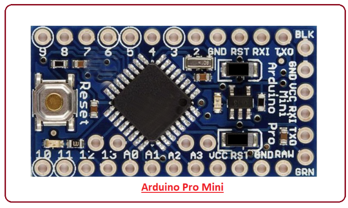
Introduction to Arduino Pro Mini
- Arduino Pro Mini is a microcontroller board developed by Arduino.cc and comes with Atmega328 microcontroller incorporated inside the board.
- This board comes with 14 digital I/O out of which 6 pins are used for providing PWM output. There are 8 analog pins available on the board.
- It is very small as compared to Arduino Uno i.e. 1/6 of the total size of the Arduino Uno.
- There is only one voltage regulator incorporated on the board i.e 3.3V or 5V based on the version of the board.
- The Pro Mini runs at 8 MHz for the 3.3V version which is half than Arduino Uno board that runs at 16MHz.
- There is no USB port available on the board and it also lacks built-in programmer.
- The labeling on the regulator defines the version of the board i.e. KB33 represents 3.3V edition and KB50 represents 5V edition. However, the board version can also be indicated by measuring the voltage between Vcc and GND pin.
- This board doesn’t come with built-in connectors that give you the flexibility to solder the connector in any way you can, based on the requirements and space available for your project.
- Like other Arduino boards, Arduino Pro Mini is open source i.e. you can modify and use the board according to your requirements as all the data and support related to this board is readily available.
- Overcurrent protection ability is another feature that makes this device safe to use in the applications where passing current can affect the overall performance of the project.
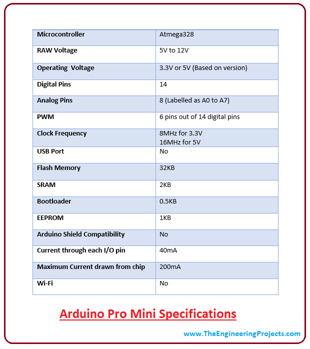
- It comes with a flash memory of 32KB out of which 0.5 is used for a bootloader. The flash memory is used for storing the code of the board. It is a non-volatile memory and stores information even if the connection with voltage supply is lost.
- SRAM is a Static Random Access Memory which is 2KB. RAM memory is highly volatile in nature and mainly depends on the constant source of power supply.
- EEPROM comes with a memory of 1KB. It is a read-only memory (ROM) which can be erased and reprogrammed. This memory can be erased by using higher than normal electrical signals.
- Following figure shows the specifications of the board.
- The Arduino Software called IDE (Integrated development environment) is used to program the board. The code we write to program the board is called a sketch.
- Like other boards available in the market, Arduino Pro Mini also comes with built-in LED which will blink as we compile and run the relevant program on the board.
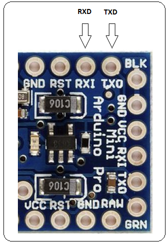
Arduino Pro Mini Pinout
Following figure shows the pin diagram of the Arduino Pro Mini Board.
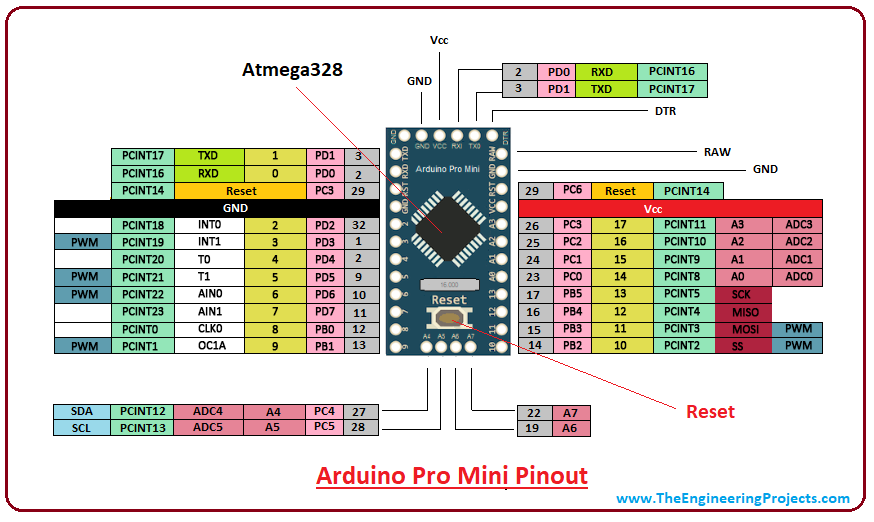
- This board is very small and compact as compared to other boards. However, small size makes this device compatible and useful for most Arduino Projects.
Pin Description
Each pin on the Pro Mini board comes with a specific function associated with the board.
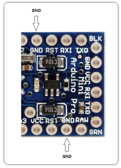
GND. There are more than one ground pins incorporated on the board which can be used as per requirement when more ground pins are needed for the project.
TXD & RXD. These pins are used for serial communication. TXD represents the transmission of serial data. RXD is used for receiving the data.
AIN0 and AIN1. These pins are connected to the internal comparator.
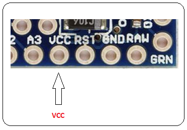
VCC. It represents the regulated voltage which can be regulated to either 5V or 3.3V based on the version of the board.
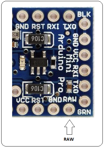
RAW. This pin is used for supplying raw voltage to the board. It is connected to unregulated power supply ranges from 5V to 12 V.
PWM. There are 6 digital pins labeled as 3,5,6,9,10, and 11 available on the board that provide PWM (pulse width modulation). This process is used for producing analog results with digital resources.
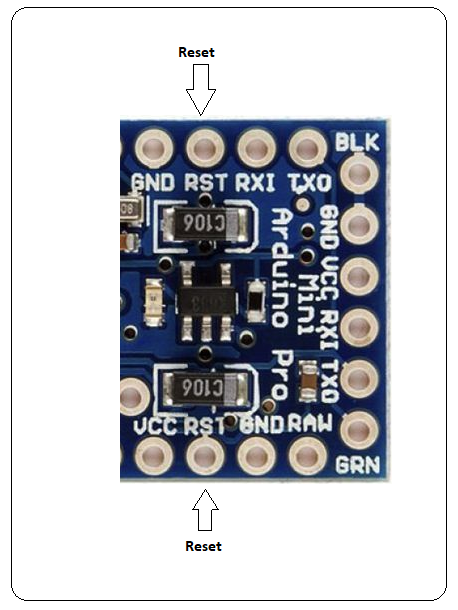
Reset. The Pro Mini board comes with a reset pin which comes handy where board hangs up in the middle of the running program. Making this pin LOW will reset the board.
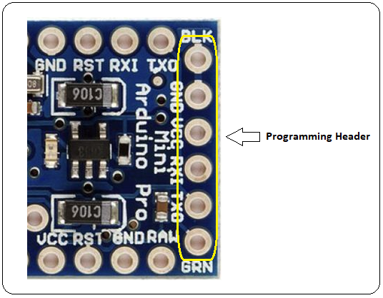
Programming Header. FTDI six-pin header is connected on these pins which is used to program the board.
SPI. It represents Serial Peripheral Interface which is mainly used for the transmission of data between microcontrollers and other peripherals like sensors and registers. Four pins 10(SS), 11(MOSI), 12(MISO), and 13(SCK) are used for this purpose.
Analog Pins. There are 8 analog pins available on the board labeled as A0 to A7. These pins are used to input analog signals and they come with a total resolution of 10bit.
External Interrupts. There are two external interrupts available called T0 and T1. They are also known as hardware interrupts.
I2C. A4 and A5 are used for developing I2C communication. A4 is known as serial data line (SDA) which holds the data and A5 shows serial clock line (SCL) which provides data synchronization between the devices.
How it is different than other Boards
- Most of the Arduino boards come with a USB port that is used to send the program from the computer to the board. However, in case of Arduino Pro Mini, all of the USB circuitry is removed to make it as compact and small as possible. You can program the board using USB to serial converter cable. The FT232RL USB serial module is very handy and preferable for programming this board. A six pin FTDI header can be connected to USB to serial converter that provides the USB power.
- If you have already worked on Arduino Uno board, then no need to buy USB to serial converter cable as you can program the Pro Mini using Uno board. Make sure, the Pro Mini version you are working on comes with 5V regulation as it runs at 16MHz like Arduino Uno board. Programming your 3.3V Pro Mini board will not be compatible with Arduino Uno board, hence making it very difficult to program the 3.3V version of Pro Mini board.
- The form factor is another major difference that makes this device unique.
- Pro Mini comes in very small and compact size which makes this device suitable for most of the applications. But small size comes with one limitation i.e. it doesn’t compatible with Arduino Shields unless you hard-wire the board with Arduino Shield.
Arduino Pro Mini Set Up
- First, you need to install the Arduino IDE software to your computer which is a standard software used to program the board.
- Connect the board with USB to Serial converter (FTDI serial module) that is used to transfer the program from computer to the board.
- Write the program in the IDE software in C language.
- No separate burner is required to burn the code. You can directly burn the code in the IDE software and transfer it to the board.
- Once you have burned and transferred the program to the board, next step is to power the board to make it compatible with your project.
- Apart from using FTDI serial module, there are two ways to power the board. You can power the board through the RAW by setting the voltage range anywhere between 5V to 12V. It will automatically regulate to 3.3V based on the version of the board. However, if your project comes with a regulated voltage of 3.3V, then you can connect it directly to the Vcc pin of the board. Make sure, the board version is KB33 that runs at 3.3V, another version KB50 will run at 5V.
- These two ways of powering up the board are useful when you have disconnected the board with the computer and already burned the program using FTDI module.
Applications
There are many applications of Arduino Boards, but the small size and ease of use make Arduino Pro Mini stand out from others, especially where space requirement of the project is highly concerned.
- IoT applications
- Mobile applications
- Embedded systems
- Home automation
- Display Systems References:
[1]https://www.theengineeringprojects.com/2018/06/introduction-to-arduino-pro-mini.html
No hay comentarios.:
Publicar un comentario